
CESE Features
 PDF version PDF version |
- About this document
- Installation
- Starting CESE
- Getting help
- Installing models
- Controlling model parameters
- Performing simulations
- Viewing results
- Printing and saving results
- Clamp mode and clamping signals
About this document
This document is a brief description of the Cell Electrophysiology Simulation Environment (CESE). This is a short overview of the application features and is not a full user's guide.
Installation
Copy the archive file your downloaded to the destination directory and unpack (Windows users — click on the archive and select destination directory). The cese directory will be created.
Starting CESE
Windows users can use native launcher (cese.exe) in cese directory to start CESE.
In addition, there are 2 script files included in the root of the distribution — cese.bat for Windows and cese.sh for UNIX (bash). Run these scripts to start CESE. When you run CESE for the first time, a local installation directory (cese-1.4) will be created for each user. Local files and settings are stored in this directory.
The default local installation directory structure for CESE is outlined below:
cese-1.4 Local installation root

   cellml/ Location for CellML models
   models/ Default location for the model files
   parameters/ Default location for the model parameter files
   records/ Default location for the clamping protocols
   results/ Default location for the simulation result files
Getting help
The online documentation is included in CESE distribution. Press F1 or select Help/Contents in the menu at any time to access information about the current state of a program. Use "What's this" feature ![]() to obtain help on a particular interface element.
to obtain help on a particular interface element.
Installing models
All models located in the /bin/models directory of the distribution and in the cese-1.4/models local installation directory will be installed automatically during CESE startup. To install models from another location, use Model/Model Manager command ![]() in the main menu.
in the main menu.
Controlling model parameters
Model Selector.
The model selector allows you to switch between the installed models.
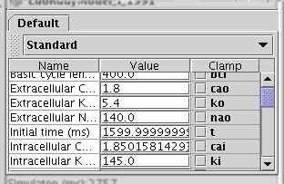
Parameters Table.
You can set model parameters values in the table ("Value" column). Click on the parameter you want to change, enter new value, and press <Enter>. If the new value is valid, it will be changed. You can save current model parameters at any time using File/Save Parameters ![]() and File/Save Parameters As commands. The saved model parameters can be loaded later using File/Open Parameters command
and File/Save Parameters As commands. The saved model parameters can be loaded later using File/Open Parameters command ![]() . To reset model to its initial condition use File/New Parameters
. To reset model to its initial condition use File/New Parameters ![]() .
.
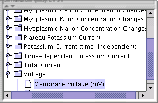
Display Tree.
Below the parameters table is a display tree. Here you can select model parameters that will be displayed as simulation results. You can select more than one variable — press <Ctrl> or <Shift> while selecting variables.
Performing simulations
After model parameters are set and display variables are selected press Start Simulation (F5) button ![]() to run simulation.
to run simulation.
To select where to output the results (into the new or top results window) use Select new/top window button ![]() on the main tool bar.
on the main tool bar.
Note that you can continue to work with the program interface during the simulations.
To set the simulation-related properties use a Simulation Options dialog (Model/Simulation Options ![]() in the menu).
in the menu).
Viewing results
When simulation is finished the selected data will be displayed in the new or added to the top Results View window.
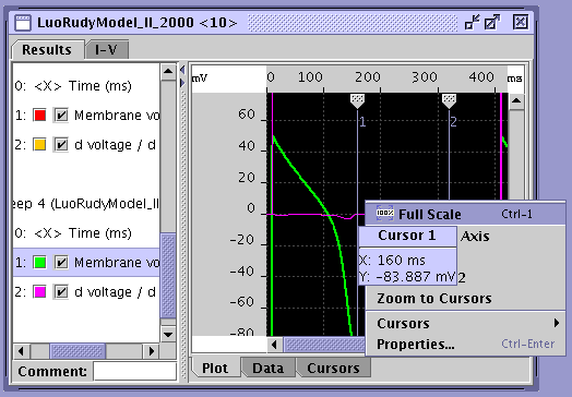
Results View Window.
Each Results View window contains a data area with 2 axis.
To zoom onto the region of data, press <Ctrl> and while pressing drag with a mouse (pressing left mouse button) — you will see a rectangle representing zooming area. Release a mouse button (still keeping <Ctrl> depressed), and scale changes.
Dragging with a mouse from top left to bottom right will set a Zoom In mode, whereas dragging in the opposite direction will change it to Zoom Out mode.
Return to the full scale is simple — press <Ctrl> and double click with a left mouse button. You can also click with a right mouse button and select Full Scale from the context menu.
To zoom in on one axis only, <Ctrl>-drag with a mouse in the axis area. You can also use <Ctrl>-double-click or use context menu for the axis to return to the full scale.
On a left side of each Results View window there is a legend panel (hidden by default). In the Legend Tree you can select a channel and change its visual properties, change plot type, or hide it. You can also specify comment which will be printed with the data.
Printing and saving results
To print results select a Results View window and choose File/Print Results command ![]() in the main menu. Select File/Print Preview
in the main menu. Select File/Print Preview ![]() to get a preview dialog where you can change different page setup options.
to get a preview dialog where you can change different page setup options.
To save results as ASCII, ATF (Axon Text File, compatible with Axon's pClampTM software), NetCDF data files, or PNG and SVG image files, select a Results View window and choose File/Export Results command ![]() in the main menu.
in the main menu.
Clamp mode and clamping signals
You can specify a command that will control certain model parameter during simulation run (see clamp tutorial for details).
All signals and records are stored as XML documents and can be opened in any text editor. Simple XML editor is built into the environment, select Record/Record Editor ![]() to invoke.
to invoke.
To use a clamp command, open a record file (Record/Open Record command ![]() in the main menu). The environment will go into the clamp mode, and certain variables will be marked as clamped in the model properties table (based on the information in the record file). Start simulation as usual, using Model/Start Simulation (F5).
in the main menu). The environment will go into the clamp mode, and certain variables will be marked as clamped in the model properties table (based on the information in the record file). Start simulation as usual, using Model/Start Simulation (F5).
After you selected a record file, you can test its content by selecting Record/Test Record command ![]() in the main menu.
in the main menu.